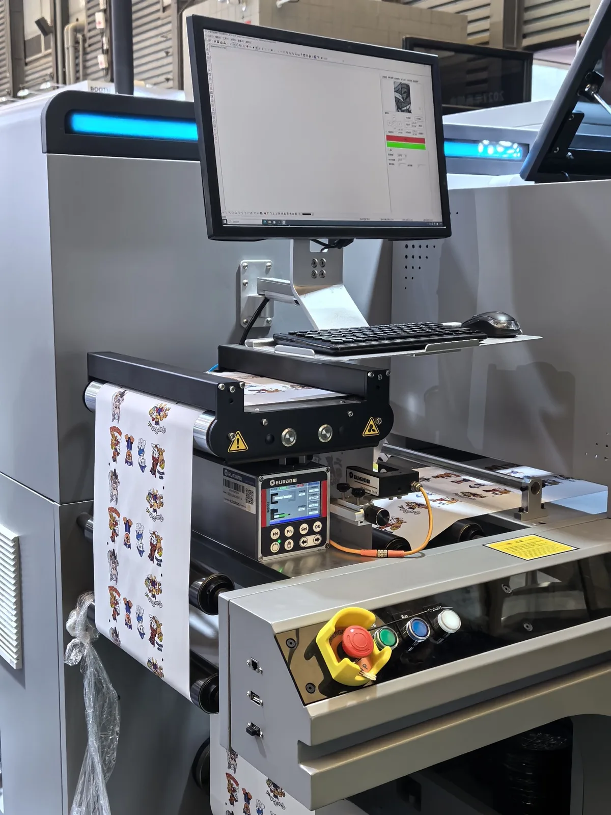
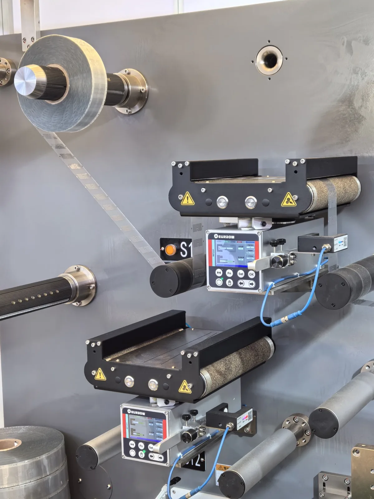
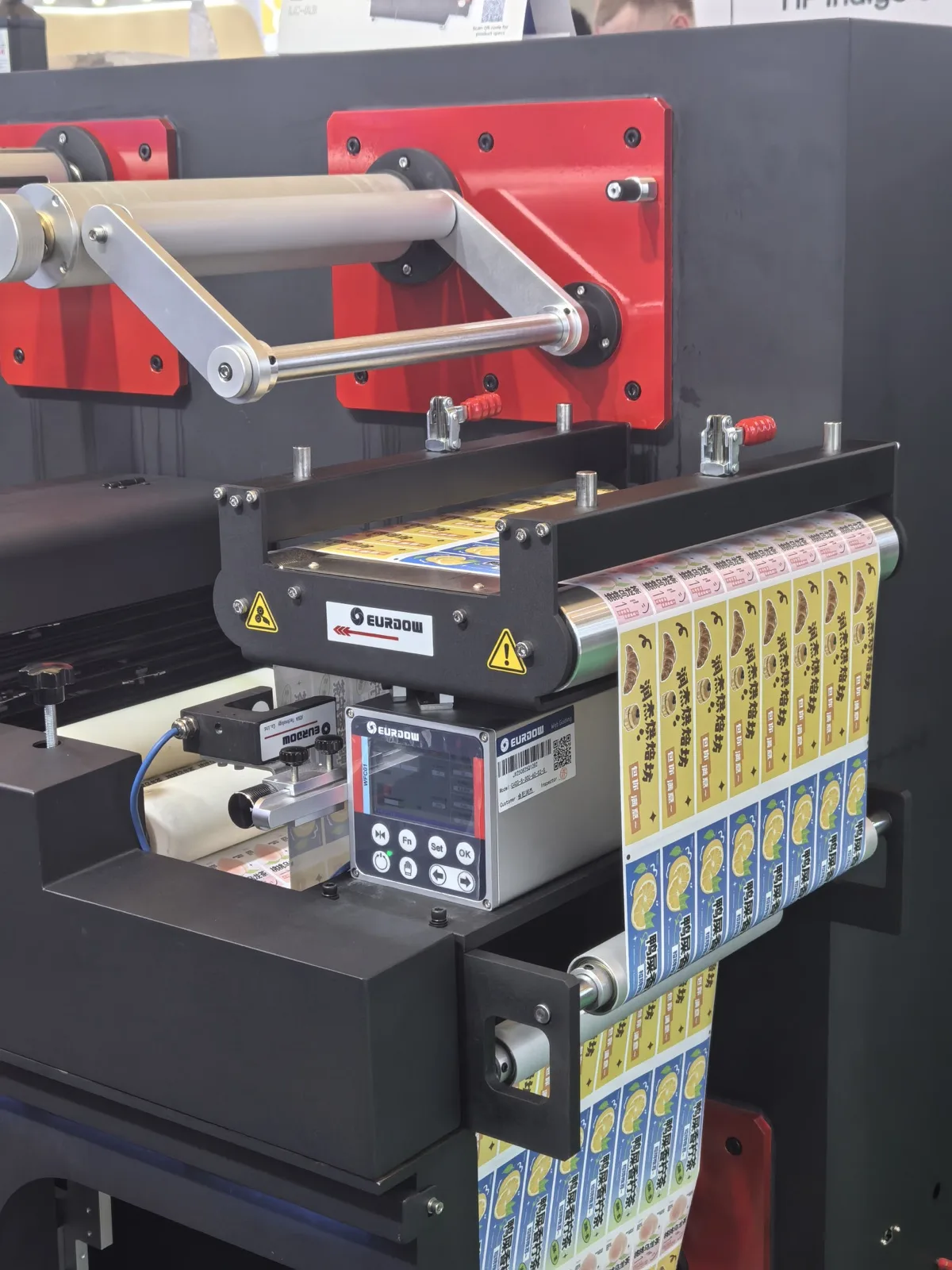
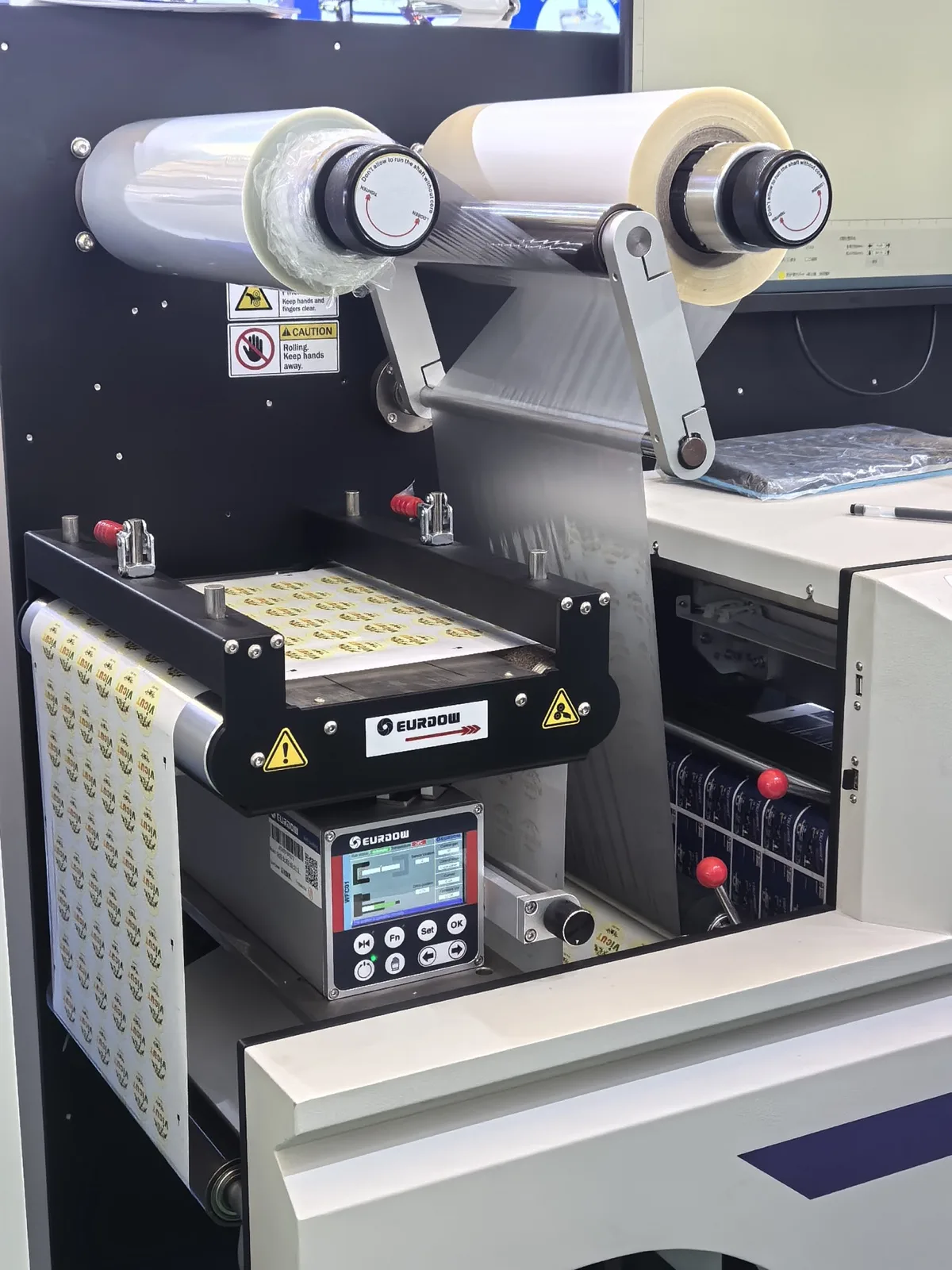
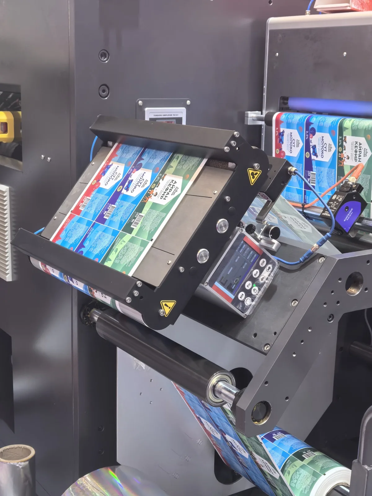
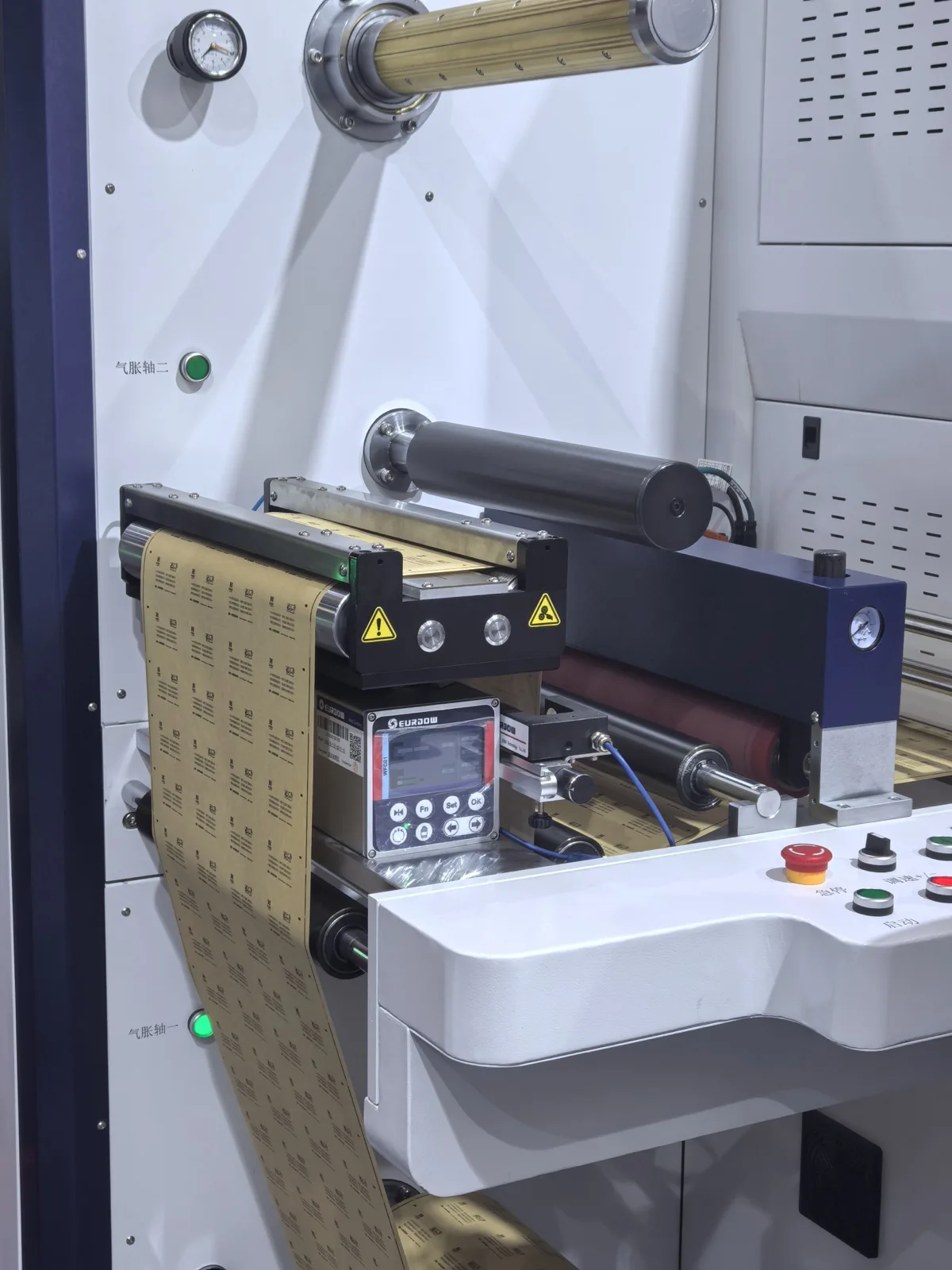
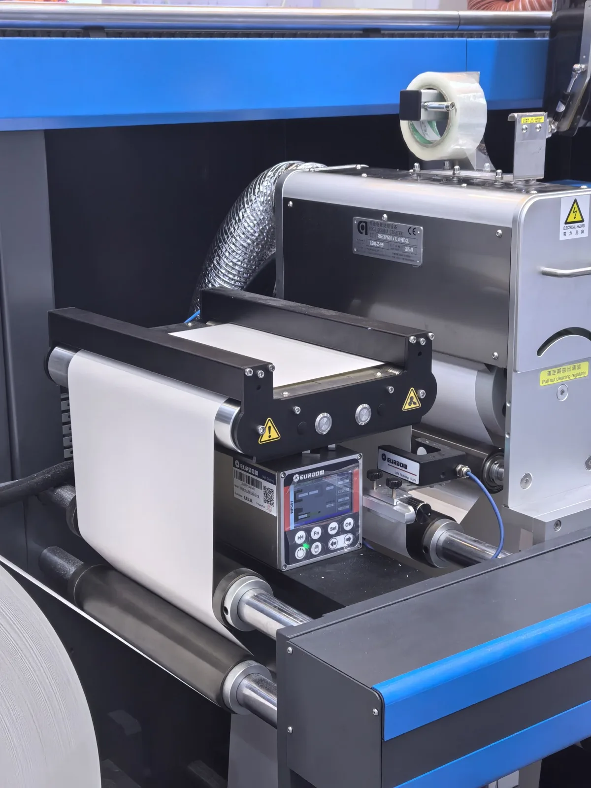
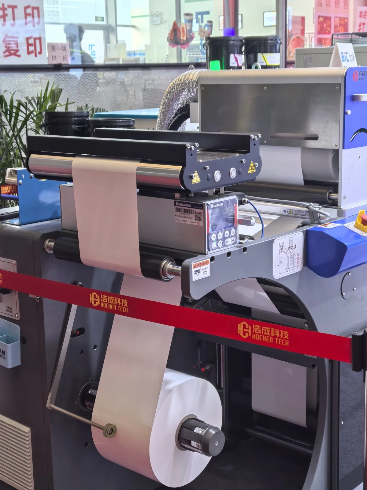
| Machine type | Likely guide location, control sequence and integration route | Flexo, digital, intermittent rotary, inspection, die-cutting or finishing |
| Installation section | Correction principle and distance to the controlled process | Marked web-path drawing showing unwind, rollers and target process |
| Web material | Sensor principle and web-support requirements | Paper, film, foil, laminate; transparent, translucent or opaque |
| Web width | Roller length, clear opening and frame envelope | Minimum, normal and maximum width |
| Line speed | Control-response review and mechanical stability | Normal and maximum operating speed |
| Edge, center or line guiding | Number and type of sensors plus control logic | Reference to follow and expected product changeover |
| Available installation space | Frame depth, mounting orientation and maintenance clearance | Length × width × height, photos and nearby obstructions |
| Roller length and frame dimensions | Mechanical configuration and compatibility with the web path | Required face length, roller diameter preference and mounting points |
| Sensor type | Ability to detect the chosen edge or reference | Material samples or clear description of opacity, contrast and edge condition |
| Standard unit or customized frame | Engineering scope, dimensions and machine-interface responsibility | Preferred standardization level and target machine series |
| Manual or pneumatic splicing table | Operator access, air supply and frame arrangement | Splicing method, roll-change workflow and available compressed air |
| New machine or retrofit | Freedom to change the layout, brackets and controls | 3D/layout drawing for new builds; photos and measurements for retrofits |