A web guiding system is an automatic control system that keeps a moving web in its correct lateral position as it travels through a machine. A sensor measures where the edge or a reference line actually is, a controller compares that measurement with the target position, and an actuator moves a guide frame or roller to bring the web back. The correction runs continuously for as long as the line is running.
What a Web Guiding System Is
In converting and printing, a web is any continuous flexible material that is unwound from a roll, processed, and wound back up: paper, plastic film, aluminum foil, laminates, nonwovens, label stock, textiles. The material travels over a series of rollers, and in an ideal machine it would follow exactly the same path every metre of the way.
It does not. Real material moves sideways as it runs. A web guiding system exists to measure that sideways movement and cancel it out, so that the web arrives at each process station in the position the process expects.
It is worth separating two things that are often confused. Web guiding controls lateral position — how far the web sits to the left or right of where it should be. Web tension control governs the longitudinal pull along the web as it runs. They are different loops solving different problems. A line with unstable tension can still be perfectly guided, and a line with perfect tension can still wander badly. Diagnosing one as the other is one of the most common mistakes in web handling.
The short version: tension controls how hard the web is pulled. Guiding controls where the web sits. If the problem is a crooked roll or drifting registration across the width, it is a guiding problem. If it is wrinkles, breaks or telescoping rolls, look at tension first.
Why the Web Drifts in the First Place
Understanding what a web guide does is easier once it is clear what it is fighting. Lateral drift is not a fault in a well-built machine; it is the normal consequence of running real material through real mechanics.
The incoming roll changes as it unwinds
As the unwind roll gets smaller, the angle at which the web leaves the roll changes. If the roll was not wound perfectly straight in the first place — and very few are — that error is delivered into the machine continuously, and it changes as the diameter drops. A roll that runs true at full diameter can wander noticeably in the last few hundred metres.
Rollers are never perfectly parallel
A web follows the roller it is wrapped on. If a roller is even slightly out of parallel with the one before it, the web will steer toward one side. Machine frames flex, bearings wear, and rollers that were aligned at installation drift over years of production. Small angular errors accumulate along a long web path.
The material itself is not uniform
Baggy edges, thickness variation across the width, camber in the material, and telescoped or dished rolls all push the web sideways. Extruded and cast films frequently have a thicker or looser edge. Slit rolls inherit whatever error the slitter left behind.
Tension variation feeds into position
Tension and position are not fully independent. A change in tension changes how the web tracks over a roller, particularly on soft, elastic or thin materials. Tension upsets at splices, roll changes and speed ramps often show up as a visible lateral movement.
Splices, cores and roll changes
Every splice is a discontinuity. Core eccentricity, a shifted core in the chuck, or a roll loaded slightly off-center introduces a step change in position that no amount of careful mechanical setup will prevent.
None of these can be eliminated by aligning the machine once. They are continuous, changing disturbances — which is exactly why the correction has to be a closed loop rather than a one-time adjustment.
How a Web Guiding System Works
Every web guiding system, regardless of brand or size, runs the same three-step cycle.
- Detect. A sensor measures the actual position of the web edge, both edges, or a printed reference on the surface.
- Calculate. The controller compares that measurement with the target position and works out the size and direction of the error.
- Correct. The controller drives an actuator, which moves a guide frame or roller assembly, which moves the web.
The important word is closed. After the correction, the sensor measures the web again, and the new measurement includes the effect of the correction that was just made. The system never assumes its correction worked; it verifies it, thousands of times a shift.
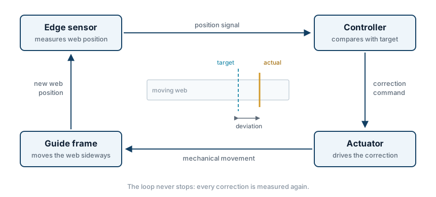
This is also why a web guide can be correctly specified on paper and still perform poorly. The loop is only as good as its slowest or least accurate element. A fast controller cannot compensate for a sensor that loses the edge on transparent film, and an accurate sensor cannot compensate for an actuator that runs out of travel. The parts have to be matched to each other, which is covered in more detail in our guide to how the controller, sensor and actuator work together.
The Four Parts of a Web Guiding System
The sensor
The sensor is where the loop starts, and it is where most guiding problems begin. Three detection principles are in common use.
- Ultrasonic. Detects the edge acoustically. Because it does not depend on optical contrast, it handles transparent, translucent and low-contrast materials that defeat light-based sensing.
- Infrared or optical. Detects the edge by the change in transmitted or reflected light. Reliable and cost-effective on opaque materials with a clean, stable edge.
- CCD or camera-based. Detects a printed line, a coating boundary or a contrast feature rather than a physical edge. Used where the reference is on the surface of the web rather than at its side.
The choice is driven by the material, not by preference. Clear film on an infrared sensor is the single most common cause of a guiding system that behaves erratically for no apparent reason. The trade-offs are set out in detail in ultrasonic vs infrared edge sensors. In the KENDORIC range, the ES100 and EDS-02 cover ultrasonic detection and the CCD01 covers line and contrast guiding.
The controller
The controller compares the measured position against the target and decides what the actuator should do. Beyond that basic function, it determines much of how the system behaves in practice: how aggressively it responds to an error, whether it can be switched between automatic, manual and center modes, how it handles travel limits and alarm conditions, and whether it can be integrated with the machine PLC or has to run as a standalone unit.
Controller capability also sets what sensors and actuators can be used with it, which is why controller selection is rarely a standalone decision. The WGC01 and PC100A are examples of digital controllers configured around the sensor and actuator they are paired with.
The actuator
The actuator converts the controller's command into physical movement. Electric actuators, driven by a stepper or servo motor through a screw or gear mechanism, dominate modern systems: they hold position without continuous power, integrate cleanly with digital controllers, and need no compressed air or hydraulic supply. Older installations often use pneumatic or electro-hydraulic actuators, which is one reason ageing guides are frequently replaced rather than repaired.
Three parameters matter when sizing one: stroke, meaning how far it can move; thrust, meaning how much force it can apply against the web, the frame and its own friction; and response, meaning how quickly it can move without overshooting. The ACT01 and ACT03 are typical electric actuators for converting-line duty.
The guide frame or correction structure
The last part is mechanical, and it is the one most often overlooked. Something has to physically move the web, and that something has to be rigid enough not to deflect, free enough not to bind, and geometrically arranged so that its movement actually translates into lateral web displacement.
A sensor, controller and actuator that are all correctly chosen will still guide badly if they are bolted to a structure that cannot move the web cleanly. This is the usual reason a component-level retrofit disappoints. The distinction between a complete frame and separate components is covered in integrated guide frame vs separate components.
What the System Follows: Edge, Center or Line
Before selecting hardware, it is necessary to decide what the system should hold constant. There are three answers, and they lead to different sensor arrangements.
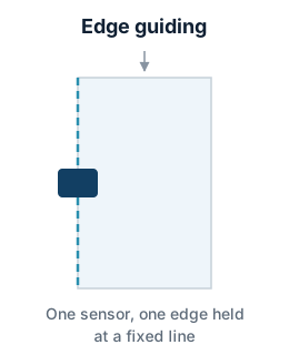
Edge guiding
One sensor watches one edge and the system holds that edge at a fixed line. This is the most common arrangement by a wide margin. It is simple, it is accurate, and it is the right choice whenever the process references one side of the web — most slitting, most printing, most laminating. Its limitation is that any variation in web width appears entirely on the opposite edge.
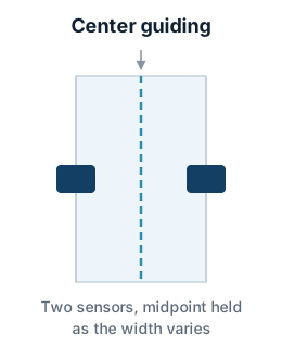
Center guiding
Two sensors, one on each edge, and the system holds the midpoint between them. Center guiding is used where the web width varies and the process needs the material centered rather than referenced to one side: trimmed webs, materials with unstable edges, and processes where symmetry matters more than absolute edge position. It costs a second sensor and a controller capable of processing both signals.
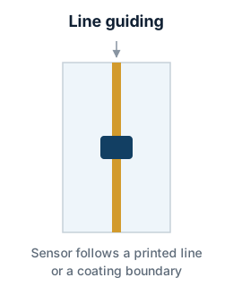
Line or printed-reference guiding
A CCD or contrast sensor follows a printed line, a register mark or a coating boundary on the surface of the web instead of its physical edge. This is the option when the edge is not a reliable reference — because it is ragged, because the printed image is what actually needs to align, or because the meaningful feature sits in the middle of the web.
Where the Guide Is Installed
The same hardware placed at a different point in the machine solves a different problem. A web guide only corrects what happens downstream of itself; it can do nothing about errors introduced after it.
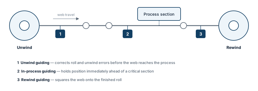
Unwind guiding
Installed just after the unwind, this position corrects the errors carried in by the incoming roll before they reach anything else. It is usually the first guide fitted to a line, because the incoming roll is usually the largest single source of lateral error. It cannot correct anything the machine itself introduces further downstream.
In-process guiding
Installed immediately ahead of a section where position accuracy is critical — a print unit, a die-cutting station, a coating head, a lamination nip. It gives the tightest control exactly where it is needed, and is often used in addition to unwind guiding rather than instead of it.
Rewind guiding
Installed just before the rewind, this position squares the web onto the finished roll. Its purpose is roll quality: clean roll edges, no telescoping, a roll that runs true on the next machine. It does nothing for what happened during the process, which is why a rewind guide alone is rarely the complete answer.
Many lines end up with two guides. The choice between them, and when both are justified, is set out in unwind web guide vs rewind web guide.
Types of Web Guide by Correction Structure
Web guides are commonly classified by how they physically move the web. The four arrangements below cover the great majority of installations.
Integrated or pivoting guide frame
A self-contained unit carrying two or more rollers on a frame that pivots or slides as a whole. The web enters, wraps the rollers, and leaves displaced sideways. Because the mechanics, the actuator and often the sensor mounting come as one assembly, it is the simplest option to specify and install, and the usual choice for a new machine or a section with no existing movable structure. It requires a defined amount of web path length. The integrated web guiding frame page covers the format in detail.
Steering roller guide
A single roller is pivoted about an axis to steer the web laterally as it passes over. It needs less installation space than a full frame and suits mid-process positions, but it depends on adequate wrap angle and on sufficient free span downstream for the steering effect to develop.
Moving unwind or rewind
Instead of moving the web, the entire unwind or rewind station moves on a slide. This is the standard approach for correcting errors at the roll itself, especially with heavy rolls or wide webs where deflecting the web with a frame would be impractical. It moves a large mass, so it responds more slowly than a frame guide.
Displacement or offset pivot guide
A frame that displaces the web laterally without changing the exit angle of the web path. It is used where the downstream geometry must not be disturbed, typically in tight machine layouts.
Typical Applications
Label printing and finishing. Narrow-web lines with multiple print, die-cutting and inspection stations, where a fraction of a millimetre of drift shows up as a registration error. Often two guides on one machine. See web guiding for label printing machines.
Slitting and rewinding. Slitters inherit whatever error the parent roll contains, and any lateral drift becomes an edge-quality defect on every finished roll. Guiding at the unwind is close to standard. See choosing a web guiding system for a slitting machine.
Flexible packaging and film converting. Transparent and metallized films, wide webs, high line speeds. This is where sensor selection matters most, and where ultrasonic detection is common.
Coating and laminating. Two or more webs must be brought together in exact lateral alignment. Each web typically needs its own guide, and the tolerance is set by the product rather than the machine.
Nonwovens and paper converting. Wide, soft and often irregular materials with variable edge quality, where the correction travel needed can be considerably larger than on film lines.
Application-specific notes for each of these are collected on the industries page.
What a Web Guiding System Actually Changes on the Line
The benefits of web guiding are easier to judge as specific, observable effects rather than as general claims.
- Edge trim can be reduced. A web that holds position needs a smaller safety margin at the edge, and that margin is waste on every metre produced.
- Registration holds across the width. On multi-station printing, lateral drift appears directly as color-to-color or die-to-print misregistration.
- Slit edges stay clean. Drift at the slitting station produces width variation and ragged edges on the finished rolls.
- Roll ends stay square. Rolls with stepped or dished edges are rejected by customers and cause problems on the next machine.
- Roll changes take less time. Automatic correction removes the manual re-centring that follows every splice or new roll.
- The line can run faster. Lateral stability is frequently the practical limit on line speed, not the process itself.
Common Web Guiding Problems and What They Usually Mean
Most calls about a web guide that "does not work" fall into a small number of patterns, and the pattern usually points at the cause.
The web oscillates around the target instead of settling
Continuous hunting normally indicates that the loop is reacting too strongly for the mechanics it is driving, or that the sensor is too close to the point of correction to see a settled result. Controller gain, sensor position and the free span between the guide and the sensor are the three things to look at. On very light or elastic materials, the web itself can also introduce the delay.
The actuator runs to its travel limit and stays there
This is almost never a control fault. It means the incoming error is larger than the correction range available, which points either at the roll — badly wound, telescoped, a shifted core — or at an actuator whose stroke was sized for average rather than worst-case conditions. Machine alignment upstream is worth checking before anything else.
The system loses the web on transparent or metallized material
A sensor selection issue, not a controller issue. Optical detection needs contrast that clear film does not provide, and highly reflective surfaces can confuse it in the opposite direction. Confirming the sensor type against an actual material sample is the reliable fix.
Guiding is stable but the finished roll is still not square
If the web is demonstrably held at target during running and the roll still builds unevenly, the problem is more likely in tension or winding than in guiding — taper tension, nip pressure, or a rewind that is not tracking the guide. Adding a second guide will not correct a winding fault.
Correction is slow or hesitant
Mechanical before electrical: binding in the slides, an under-sized actuator working against friction, insufficient wrap on a steering roller. An actuator that is at its thrust limit behaves very much like a controller that has been detuned.
How to Specify a Web Guiding System
Most of the information needed to configure a web guide describes the machine and the material rather than the guide itself. Having it ready shortens the process considerably.
- Web material and thickness, including whether it is transparent, translucent, opaque, coated or metallized
- Web width, minimum and maximum
- Line speed, normal running speed and maximum
- Guiding position — unwind, in-process or rewind
- Guiding reference — edge, center or printed line
- Free span available before and after the guide
- Correction travel required, based on the worst incoming error rather than the typical one
- Installation space and the existing roller arrangement
- Power supply and control interface, including whether PLC integration is required
- For an existing machine: photographs of the web path, the current guide if there is one, and a description of the problem being solved
For a retrofit, the single most useful item is a photograph of the web path. It answers questions about free span, roller arrangement and mounting space faster than a specification sheet can.
KENDORIC configures web guiding systems around this information rather than from a catalogue number. The full component range and the selection logic behind it are on the web guiding system page.
Frequently Asked Questions
What is the difference between web guiding and tension control?
Web guiding controls the lateral position of the web — how far it sits to the left or right of its intended path. Tension control governs the longitudinal pull along the web as it runs. They are separate control loops solving different problems, and a machine can need one, the other or both.
Where should a web guide be installed on the machine?
The three common positions are just after the unwind, immediately ahead of a critical process section, and just before the rewind. Unwind guiding corrects errors carried in by the incoming roll and is usually the first guide fitted. In-process guiding holds position where accuracy matters most. Rewind guiding squares the web onto the finished roll.
Can a web guide be added to an existing machine?
Yes, in most cases. If the machine already has a suitable movable structure, a component-level retrofit of sensor, controller and actuator may be enough. If there is no movable structure, a complete guide frame is normally required. The deciding factors are the available free span, the mounting space and how much correction travel the layout allows.
Which sensor type should be used for transparent film?
Transparent and translucent films are usually guided with an ultrasonic edge sensor, because acoustic detection does not depend on optical contrast. Infrared sensors rely on the difference in light between the web and the open gap, which clear film may not provide. Metallized, coated and reflective materials should be confirmed against an actual sample.
How much correction travel does a web guiding system need?
Correction travel needs to cover the worst lateral error the line actually sees, not the average one. That error comes from roll winding quality, splices, core eccentricity and the alignment of the machine itself. A guide that reaches its travel limit and stays there is normally a sizing problem or an incoming material problem rather than a control fault.
Is a complete guide frame needed, or only the components?
It depends on whether the machine already provides a structure that can move the web. An integrated guide frame carries the rollers, the actuator and the mechanical guidance together, and is the usual choice for a new machine or a section with no movable structure. Separate components suit machines that already have a movable unwind, a steering roller assembly or suitable linear rails.
Send your machine layout for a web guiding review
Share the web path, material, width range, line speed and the section you want to guide. KENDORIC will review the application and come back with a practical sensor, controller, actuator and frame configuration.
Request an Application Review