Label Printing
Stabilize material entering printing, die-cutting, inspection or finishing sections when the web edge or printed reference moves laterally.
Application-Based Web Guiding Solutions
KENDORIC provides application-based web guiding solutions for roll-to-roll machinery.
We review the web material, machine section, guiding reference, operating conditions and installation constraints to configure sensors, controllers, actuators and guide frames for new OEM machines and retrofit projects.
Prepare your machine type, web material, web width, guiding position and a short description of the lateral-position problem.
New to web guiding? Start with what a web guiding system is and how it works.
Web Position Problems
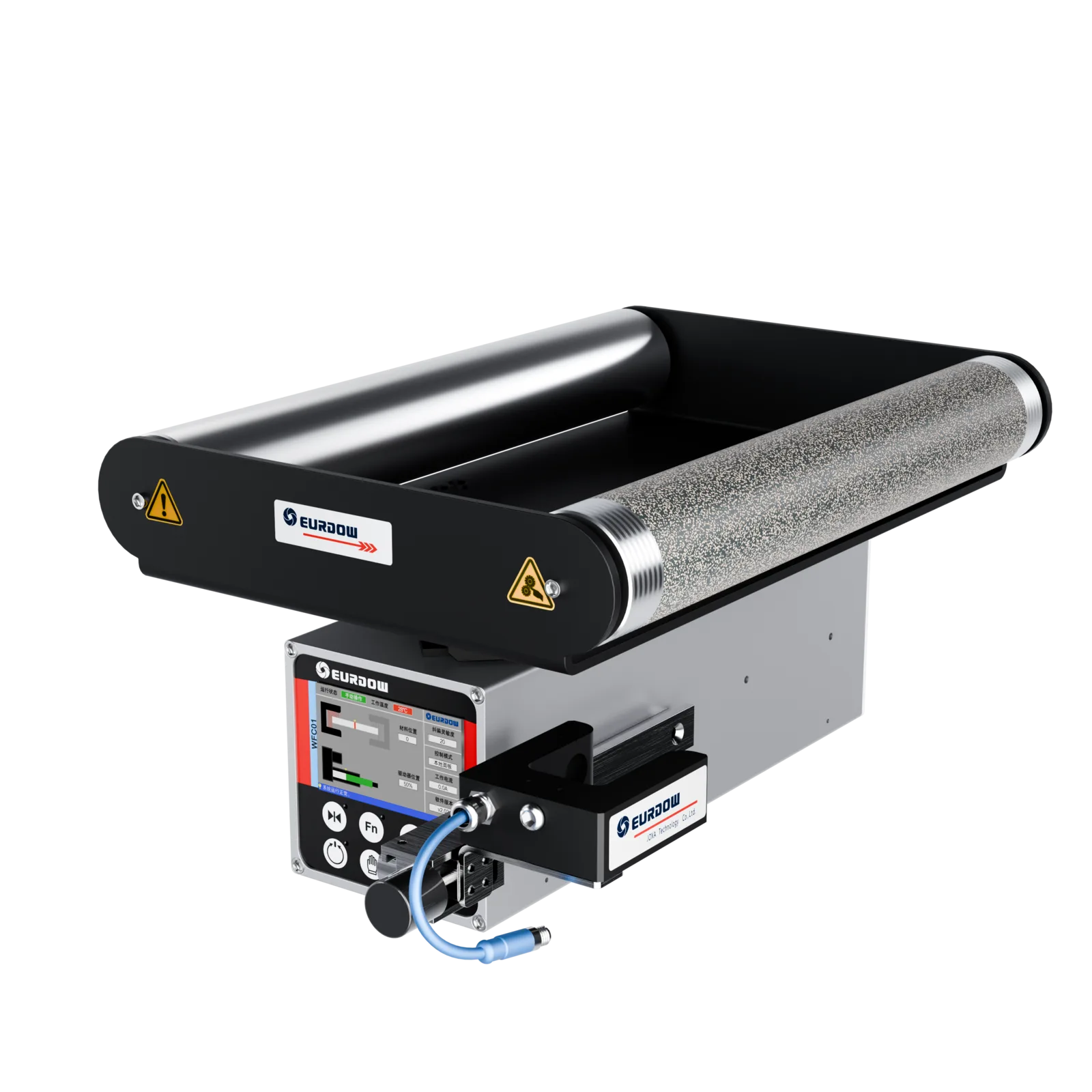
A moving web can shift laterally because of roll loading, uneven tension, material properties, roller alignment or winding conditions. The useful correction point is the position that stabilizes the web before the critical process.
Stabilize material entering printing, die-cutting, inspection or finishing sections when the web edge or printed reference moves laterally.
Control the incoming web position before the knives when lateral drift can change the relationship between the web edge and the slitting path.
Maintain the required position before coating or lamination where web alignment influences coating boundaries or layer overlap.
Guide the web entering the rewind when finished-roll edge position is the primary control objective.
Closed-Loop Correction
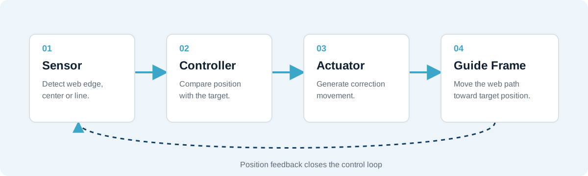
A web guiding system detects the selected reference, compares it with the target position and moves the correction mechanism. Sensor capability alone does not determine the result; the complete electrical and mechanical loop must be configured together.
A sensor monitors one web edge, both edges, a printed line, color boundary or another suitable reference.
The controller compares the detected position with the target and generates a correction command.
The actuator moves a guide frame, roller assembly, unwind stand or rewind stand to correct lateral position.
Complete Configuration
KENDORIC reviews the four functional parts as one configuration. The selected components must match the guiding reference, moving structure, required correction travel and machine interface.
Detects the web edge, center, printed line or contrast reference selected for the process.
Processes position feedback and commands the correction movement according to the guiding mode.
Provides the required stroke and force to move the selected correction structure.
Transfers actuator movement to the web path through an integrated frame, steering structure or moving roll stand.
Correction Location
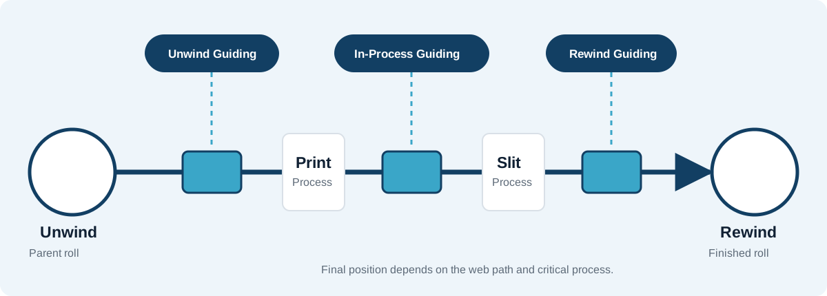
The first engineering decision is where correction should take place. The selected position should address the source of lateral movement and protect the downstream process that needs a stable web position.
Controls the incoming web as material leaves the parent roll. It is considered when roll loading or roll-edge position changes the entry position of the web.
Review: unwind movement, sensor location, available free span and the first critical downstream process.
Corrects the web close to printing, coating, laminating, inspection, die-cutting or slitting when local position control is required.
Review: correction geometry, sensor-to-process distance, web span and the reference that must be followed.
Controls the web position entering the finished roll. It is considered when the winding point or finished-roll edge is the main target.
Review: rewind stand movement, winding tension, roll geometry and sensor position.
Web guiding corrects lateral position. It does not replace the need to resolve unrelated tension, roller-alignment or winding problems.
Application Solutions
The same basic components can be used on different roll-to-roll machines, but the guiding position, sensor reference and mechanical structure must be selected for the actual process.
Unwind, pre-print, pre-die-cut, inspection and rewind guiding for label presses and finishing equipment. The system may follow the material edge, web center or a printed reference.
Review label-machine configurationIncoming-web control before the knives, unwind position correction and finished-roll edge control. Guiding should be evaluated together with winding and tension conditions.
Review slitter selection factorsGuiding for transparent, printed or laminated films where material optics, edge condition and changing roll conditions affect sensor selection.
Correction before coating, lamination or rewinding according to the required process reference, free-span geometry and material characteristics.
Sensor and correction-structure selection based on transparency, edge shape, tension, static conditions and web stability.
Edge or center guiding for printing and paper converting, with attention to dust, edge damage, web width and moving load.
Material evaluation for irregular or low-density edges before confirming the sensor type and detection arrangement.
Guiding Modes
Tracks one material edge when the edge is stable and represents the required downstream process position.
Uses both edges or a suitable width-measurement arrangement when the web must remain centered or web width changes.
Follows a printed line, color boundary or contrast feature when the printed position, rather than the physical web edge, must align with the next process.
Detection Method
No single sensor technology is suitable for every roll-to-roll material. Selection should be based on what must be detected, the material characteristics and the conditions around the detection point.
| Web or Reference | Sensor Direction | What to Confirm |
|---|---|---|
| Opaque web with a clear edge | Infrared edge sensing may be suitable. | Optical contrast, dust, ambient light and edge condition. |
| Transparent or low-contrast film | Ultrasonic sensing or another material-appropriate method may be required. | Film thickness, layers, edge shape, installation gap and material sample. |
| Printed line or color boundary | CCD or digital image sensing may be considered. | Line width, color contrast, background pattern, print variation and detection range. |
| Changing web width or center guiding | Two edge sensors or a center-measurement arrangement may be required. | Width range, center-control logic, mounting travel and controller compatibility. |
| Irregular or difficult material | Confirm the method with material evaluation. | Edge density, reflectivity, translucency, mesh structure and production environment. |
Do not select the sensor from the material name alone. Provide samples or clear photographs when transparency, contrast or edge condition may affect detection.
Compare ultrasonic and infrared edge sensorsMechanical Integration
The correction structure determines how actuator movement changes the web path. It must be reviewed together with roller geometry, available space, web span and moving load.
A matched mechanical and control unit for a suitable free web span on a new machine or retrofit.
View Integrated Frame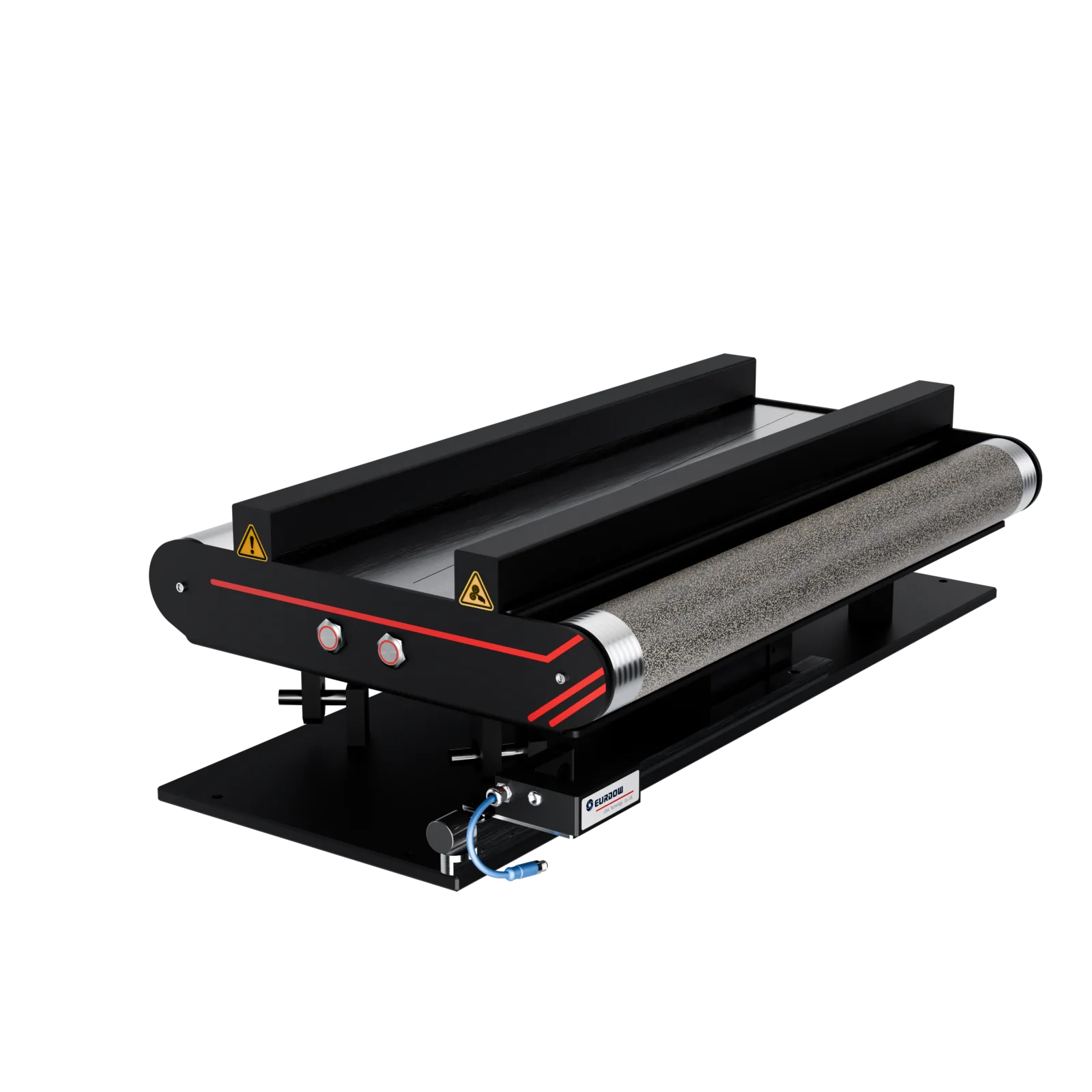
A correction structure selected according to web-path geometry, frame width and available installation space.
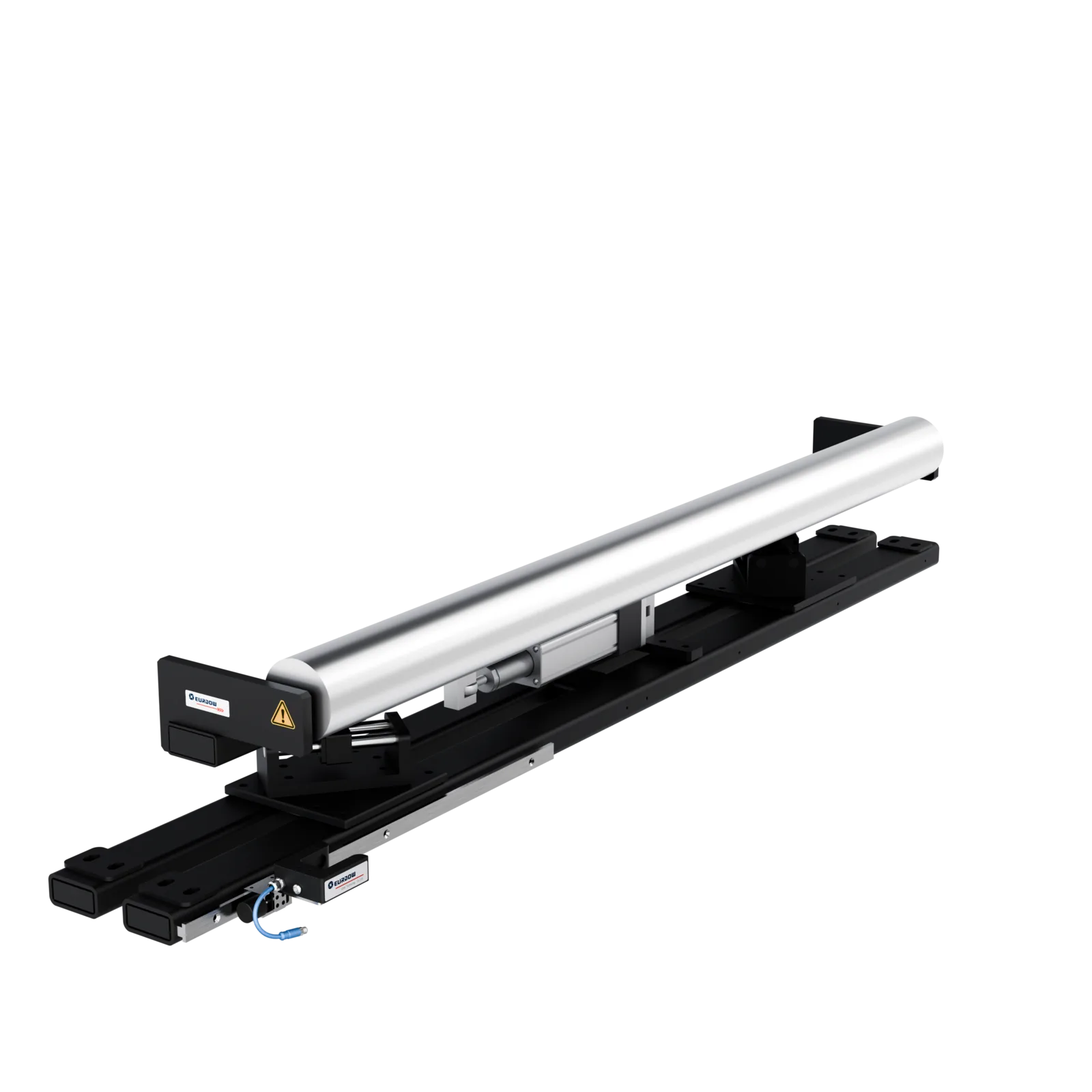
An actuator moves the roll stand laterally while the sensor monitors the web position.
Machine builders can request matched sensors, controllers and actuators for their own mechanical frame. The OEM validates frame geometry, load and machine safety.
Compare configuration pathsProject Path
The configuration path depends on whether the web path is still being designed or must fit an existing machine.
Define the critical process, guiding reference, sensor location, correction structure, installation dimensions and control interface before the machine layout is fixed.
Evaluate the current web path before selecting hardware. Available space alone does not confirm that a retrofit will correct the stated problem.
Selection Inputs
Complete application data helps avoid selecting a sensor, actuator or frame that does not fit the actual machine.
Machine type, critical process, new machine or retrofit, guiding position and edge, center or line-guiding requirement.
Material type, transparency, width range, thickness, edge condition and printed reference details.
Normal and maximum line speed, web tension if known, direction of travel and relevant environmental conditions.
Web-path drawing, available space, roller dimensions, moving load, power supply and PLC or external-control requirements.
Featured Product Models
Product models remain visible for technical comparison, but final selection should follow the application, sensor reference and mechanical structure.
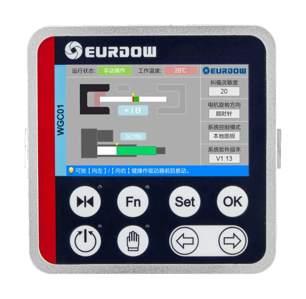
Button-operated controller option for configured edge, center or line-guiding functions.
View WGC01 controller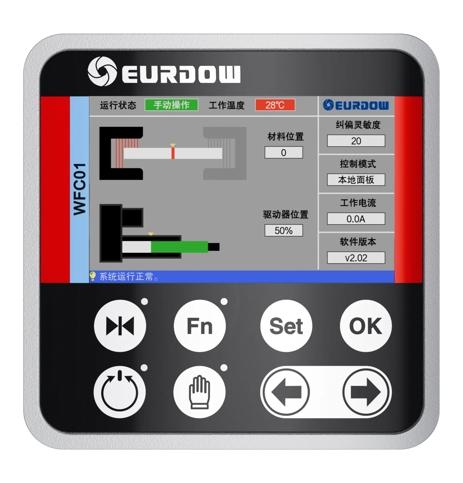
Button-operated controller for compatible edge, line and center-guiding configurations.
View WFC01 controller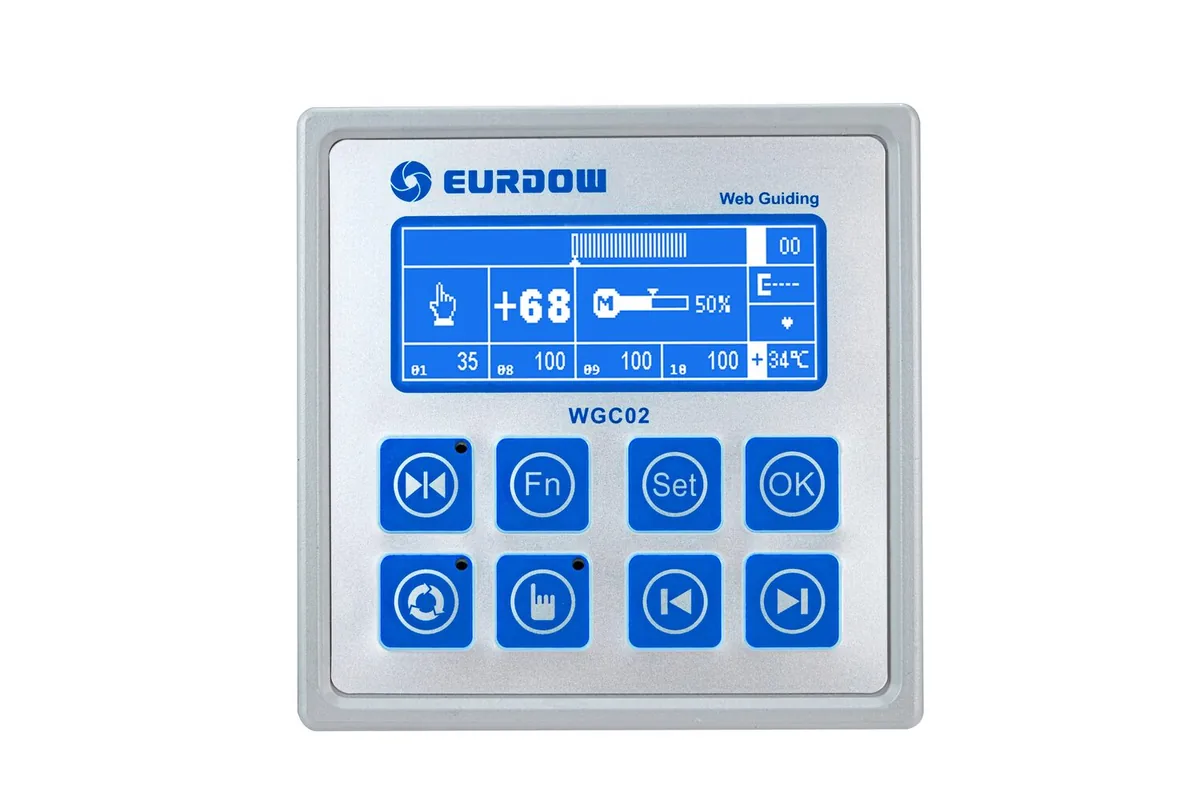
Discontinued. Replaced by WGC01 on the same interfaces — see the side-by-side comparison.
View WGC02 comparisonTouchscreen controller option for compatible edge, center, line or position-correction systems.
View PC100A controller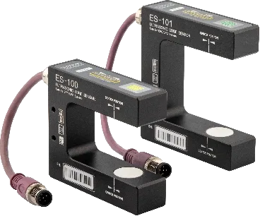
Ultrasonic edge sensor for transparent, translucent or low-contrast web materials.
View ES100 sensor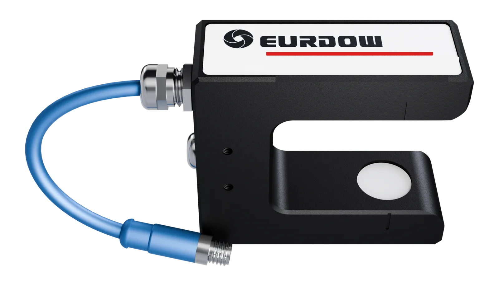
Ultrasonic sensor option where optical edge contrast is not a reliable reference.
View EDS02 sensor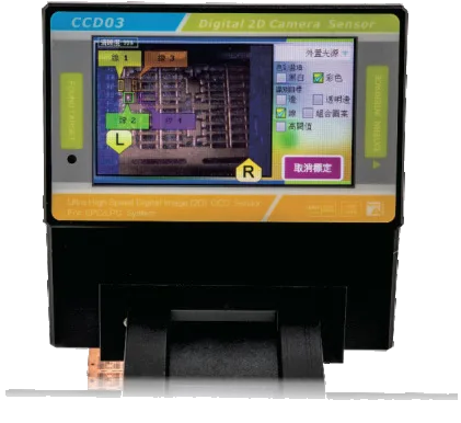
Digital photoelectric and image sensors for printed lines, color boundaries and selected difficult references.
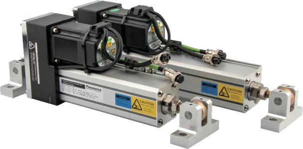
Servo actuator option for compatible standard correction structures, selected according to stroke, load and installation geometry.
View ACT01 actuator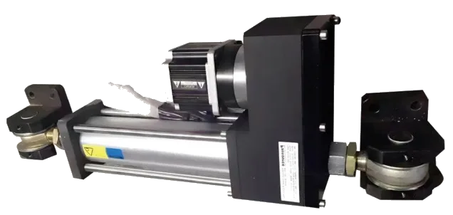
Servo actuator option for higher-load correction requirements, subject to frame and moving-load review.
View ACT03 actuatorMachine Context
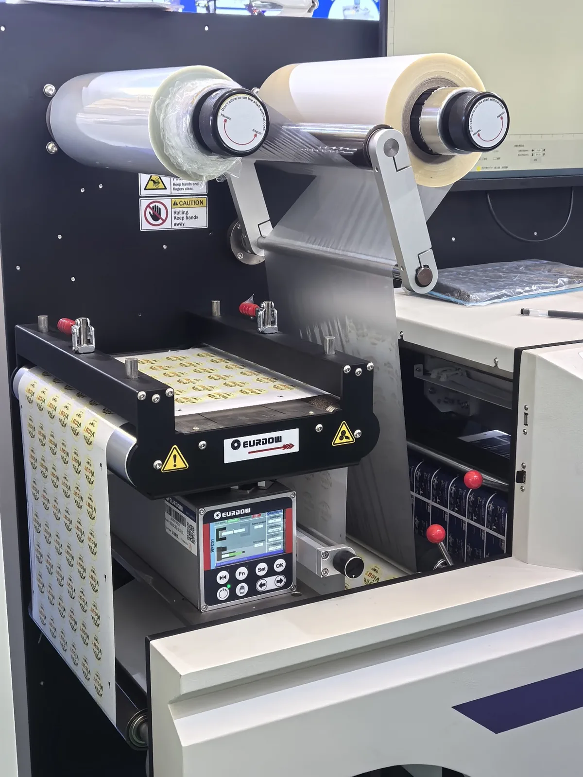
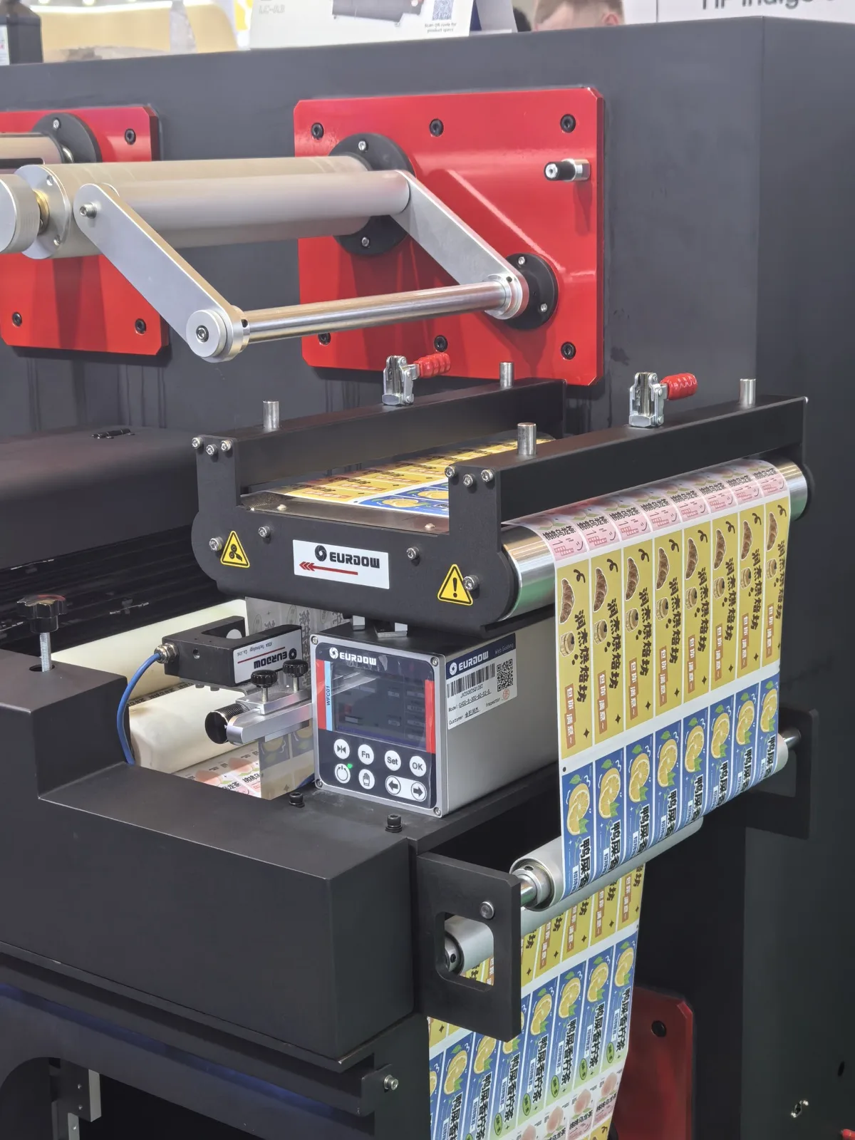
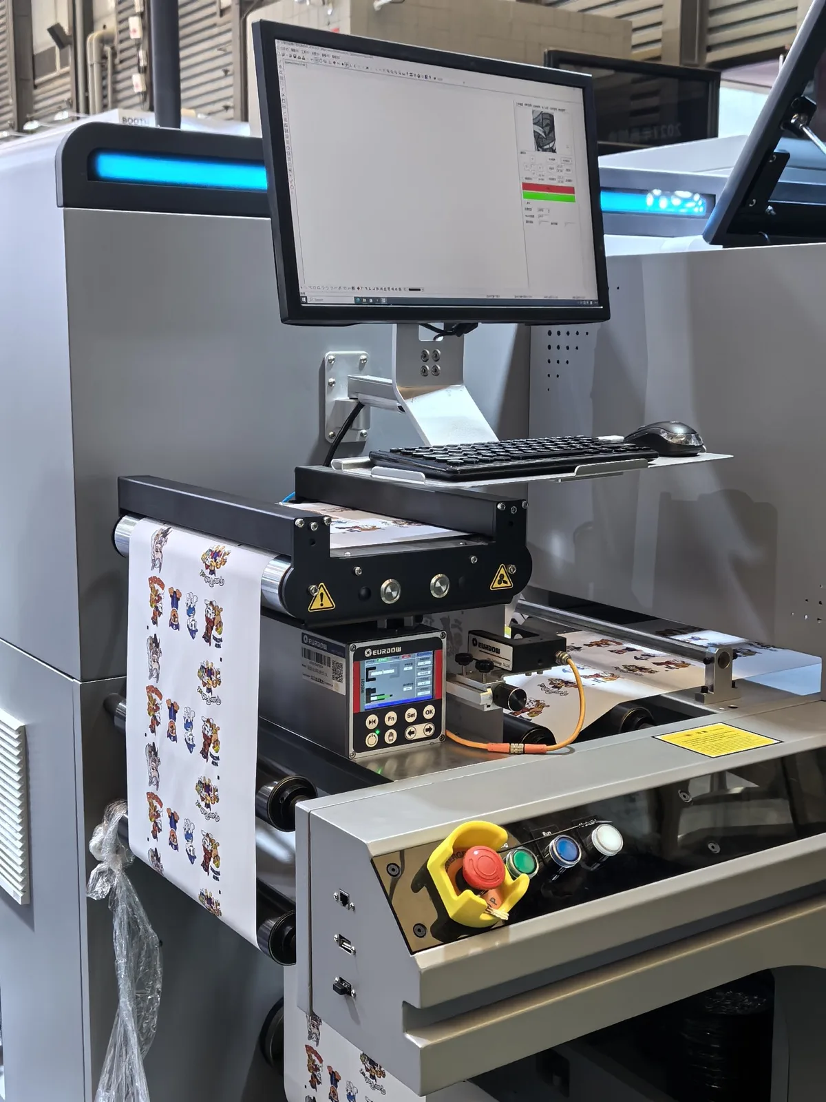
These images illustrate machine sections where integrated web guiding units may be considered. They are shown as configuration references and do not identify any company as a customer or any installation as a verified KENDORIC project.
Application Review
Recommendations begin with the machine process, web material, guiding position and required reference rather than a predetermined model.
The sensor, controller, actuator and guiding structure are reviewed as one system to reduce integration gaps.
We help organize the machine data, identify missing selection inputs and discuss installation or control-interface questions for OEM and retrofit projects.
Based on application requirements, KENDORIC works with selected manufacturing partners to provide suitable guiding systems, sensors and control solutions.
Machine, material, process position and problem.
Edge, center or line; unwind, in-process or rewind.
Sensor, controller, actuator and moving structure.
Dimensions, web path, power and control interface.
Frequently Asked Questions
Provide the machine type, web material, web width, guiding position and a description of the lateral-position problem. Line speed, machine photos, web-path drawings and PLC requirements are useful when available.
The guide should correct lateral movement before the process that requires a stable web position. The final location depends on the web path, source of deviation, free-span length, roller geometry and available installation space.
Unwind guiding controls the incoming web as it leaves the parent roll. In-process guiding corrects the web near printing, coating, laminating, inspection or slitting. Rewind guiding controls the web position entering the finished roll.
Transparent film may require an ultrasonic sensor or another sensor suitable for the actual material. Film thickness, layers, edge condition and installation environment should be reviewed before confirming the sensor.
This depends on the sensor technology, controller compatibility and material range. Samples of each material should be evaluated when one machine processes webs with significantly different optical properties.
Center guiding should be considered when the web must remain centered or when width changes make one edge unsuitable as the only reference. It normally requires detection of both edges or another suitable center-measurement arrangement.
A compatible CCD or digital image sensor may follow a printed line, color boundary or contrast reference. The printed sample, line width, background and expected print variation should be reviewed first.
KENDORIC can support configurations that include the sensor, controller, actuator and guide frame. The arrangement is selected according to the machine application, web reference and installation requirements.
Many machines can be evaluated for retrofit, but feasibility depends on the current web path, available free span, roller arrangement, moving load, correction distance and machine structure.
Web guiding corrects lateral web position. Wrinkles, telescoping rolls and other winding defects may also result from tension, roller alignment, nip conditions or winding parameters and should be evaluated separately.
Replacing a part on an existing machine? If you already have a model number such as WGC01, WGC02 or ES-100, go straight to that model page or send a photo of the nameplate on WhatsApp — no configuration data needed.
Next Step
Tell us where the web moves, which process requires a stable position and what material the machine will handle.
KENDORIC will review the available application information and discuss a suitable configuration direction.
Email
sales@kendoric.com
WhatsApp / Tel
+86 180 1318 9998