Web tension control is the system that keeps the pull along a moving web steady while the machine runs. A sensor measures the force the web is actually carrying, a controller compares it with the target, and a brake or a drive is adjusted to hold that target as the roll diameter, the line speed and the material all change during the run.
What Web Tension Is
Web tension is the force pulling along a continuous flexible material — paper, film, foil, laminate, nonwoven, label stock — as it travels through a machine in the machine direction. Too little of it and the web goes slack, wanders and wrinkles. Too much and it stretches, distorts the print, or breaks.
Tension is quoted either as a total force across the whole web, in newtons or pounds, or as a force per unit of web width, in N/mm or pounds per linear inch. The second form is the one that matters, and the reason is covered in the units section below.
It is worth separating tension from the other control loop it is most often confused with. Tension controls the pull along the web. Web guiding controls where the web sits across the machine. They solve different problems and can fail independently of each other.
The short version: if the symptom is wrinkles, breaks, a soft or telescoped roll, or registration drifting along the run, look at tension. If the web is tracking to one side, that is a guiding problem and adding tension control will not fix it.
Why Tension Cannot Simply Be Set Once
The single fact that makes tension control necessary is that the roll diameter changes while the machine runs.
A constant brake torque does not give constant tension
Tension at the unwind is torque divided by roll radius. Hold the braking torque constant and, as the roll unwinds and the radius shrinks, the tension climbs steadily — often to several times its starting value by the time the roll is nearly empty. Run the same job in reverse at a rewind and the opposite happens. This is not a fault to be trimmed out; it is arithmetic, and it is why the command to the brake or drive has to keep changing throughout the run.
Acceleration and deceleration add inertia
A full roll is heavy and resists changes in speed. Every start, stop and speed ramp adds a transient force on top of the steady-state tension. Most web breaks happen during these transients rather than at constant speed, which is why peak tension matters as much as the number on the setpoint.
The material is not a rigid body
Films stretch, and some keep stretching under sustained load. Paper responds to moisture. A web that is well behaved at one tension can behave quite differently at another, and material from a different batch may not behave the same way at all.
Splices and roll changes are step changes
Every splice, every new roll and every flying change is a discontinuity that the control loop has to absorb without letting the web slacken or snap.
How Web Tension Is Measured
A load cell does not measure tension directly. It measures the force the web applies to a roller, and then the controller works back from that to the tension in the web. This distinction matters more than it first appears, because how much force reaches the roller depends on how far the web wraps around it.
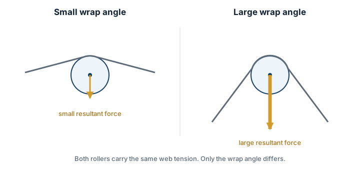
There is a practical consequence that is easy to miss when planning an installation: the wrap angle at the measuring roller must not change as the roll diameter changes. If the web comes straight off the unwind onto the load cell roller, the geometry shifts continuously through the run and the reading drifts with it. This is why measuring rollers are normally given a lead-in and a lead-out idler that fix the web path, rather than being placed directly against a roll whose diameter is moving.
Load cell mounting styles
Load cells differ mainly in how the instrumented roller is carried, and the right choice is usually decided by the machine frame rather than by the measurement itself.
- Pedestal mount — the roller sits on two mounts bolted to the frame. Compact and straightforward where there is a flat mounting surface. See the LC100A.
- Through-shaft — the roller shaft passes through the sensor body. The LS100A is a stainless, IP66 version for wet or dusty environments.
- Flange mount with self-aligning bearings — tolerates small misalignment between the two ends of the roller, which is useful on wide webs and older frames. See the LF100A and the more compact LFP100A.
- Cantilever — the roller is supported from one end. The LX100A is designed so that the reading does not change with where the web sits along the roller, which helps on narrow webs or webs that do not run centred.
Load cells produce a very small signal, so a signal amplifier normally sits between the sensors and the controller.
Load cell or dancer?
The alternative to measuring force is to control position. A dancer is a loaded roller free to move; the control system holds it at a set position, and the load applied to it sets the tension indirectly.
A dancer also does something a load cell cannot: it absorbs short tension upsets mechanically, acting as a buffer during splices and speed changes. What it does not give is a tension number. A load cell system lets an operator dial in 0.4 N/mm and know that is what the web is running at, which is what recipe-driven and quality-audited production usually needs. Many lines use both — a dancer for buffering, load cells for measurement.
Getting the Units Right
Two machines can be running the same total force and completely different processes. A 500 N pull on a 400 mm web is not the same job as a 500 N pull on a 2,000 mm web. Tension is only comparable when it is expressed per unit of web width.
| Convert from | To | Multiply by |
|---|---|---|
| lb per linear inch (PLI) | N/mm | 0.175 |
| N/mm | lb per linear inch (PLI) | 5.71 |
| pound-force (lbf) | newton (N) | 4.448 |
| kilogram-force (kgf) | newton (N) | 9.81 |
| Tension per width × web width | total force on the web | — |
A worked example: 0.5 N/mm on a 1,000 mm web is a total force of 500 N, or about 2.9 PLI. Getting this conversion wrong by a factor of ten is one of the more expensive mistakes available in web handling, and it usually happens when a value quoted in PLI is entered into a controller expecting newtons.
How Much Tension Should the Line Run?
There is no table that can answer this for a specific job, because the answer depends on the material, its thickness, its condition and what the process is doing to it. What converting-industry practice does give is a defensible way to arrive at a starting number.
Work from the material's tensile strength
The most widely used rule of thumb sets running tension at roughly 10 to 25 percent of the web's tensile strength. Testing the actual material to find where it yields and where it breaks, then working back to a five- or ten-to-one safety factor, is the method behind that range. It accounts for the fact that the weakest point across the width, not the average, is what actually breaks.
Sanity-check against the usual band
Published converting guidance puts most real production inside a fairly narrow band, which is useful as a cross-check on a calculated number.
| Reference point | PLI | N/mm |
|---|---|---|
| Most commonly cited starting point | 1.0 | 0.175 |
| Where roughly 80% of webs run | 0.3 – 3.0 | 0.05 – 0.53 |
| Where nearly all processes fall | 0.1 – 10 | 0.018 – 1.75 |
These are orientation figures, not specifications. If a calculation lands far outside this band, it is worth checking the arithmetic and the units before trusting it. And a number derived this way is a starting point for a trial run, not a setting to commission a line on — thin films, heated webs, foils and paper at high moisture content all yield at lower loads than a room-temperature tensile test suggests.
Manual, Open Loop and Closed Loop
Tension control comes in three levels, and the useful question is not which is best but which the process actually needs.
Manual
An operator sets a brake by hand and adjusts it during the run as the roll empties. It works on short runs, forgiving materials and slow lines. It depends entirely on the operator watching, and the result varies between shifts.
Open loop
The controller estimates roll diameter — from a follower arm, an ultrasonic sensor, or a calculation from line speed and roll rotation — and adjusts the command to the brake or drive to compensate for the changing radius. This removes the largest and most predictable error without needing a force sensor.
Its limit is in the name. Nothing measures the result, so anything the model does not predict stays uncorrected: a brake that fades as it heats, a roll of different material, friction that changes with the seasons.
Closed loop
A load cell measures the tension the web is actually running at and feeds it back. The controller works to the measured value, so any disturbance — predicted or not — is corrected because it shows up in the measurement.
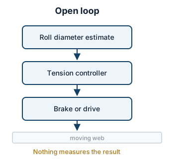
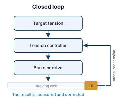
A closed loop needs four things present: a sensor, an amplifier, a controller, and an actuator that can accept the controller's command — a brake at an unwind, or a drive at a rewind. Missing any one of them and the loop cannot close.
Where Tension Is Controlled
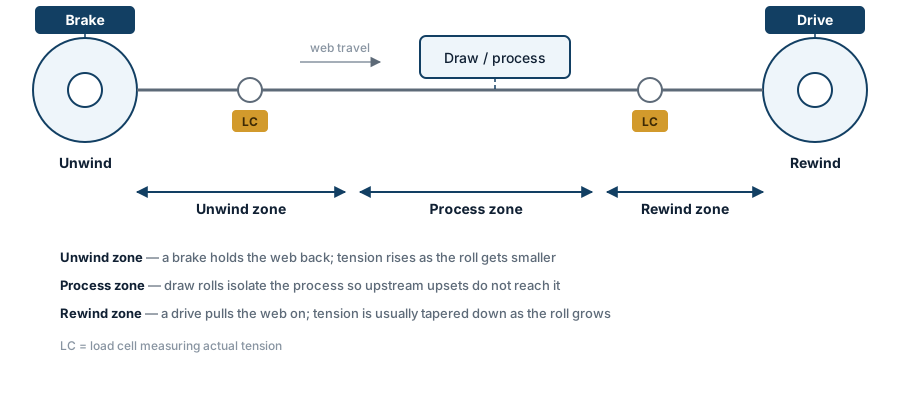
A converting line is not at one tension throughout. It is divided into zones, and each zone is held by a different device doing a different job.
Unwind
The unwind holds the web back. A brake — magnetic powder, pneumatic or regenerative — resists the pull of the machine, and the control problem is the changing roll diameter described above. This is the zone that most often gets closed-loop control first, because it has the largest inherent error.
Process
Between the unwind and the rewind, driven nip or draw rolls divide the line into sections. Their purpose is isolation: a tension upset upstream should not reach a print station or a coating head. On lines where the process itself changes the web — drying, laminating, stretching — the zones on either side may need quite different setpoints.
Rewind
The rewind pulls the web on, through a driven shaft or a torque motor. Its measure of success is not really tension but roll quality: a roll that is uniformly wound, holds its shape, and unwinds correctly on the next machine. That usually means the setpoint has to change as the roll builds, which is what taper tension does.
Taper Tension
At a rewind, holding tension constant from core to full diameter is usually the wrong thing to do.
Each new layer is wound on at whatever tension the setpoint calls for, and each layer squeezes everything already underneath it. Keep the tension constant while the diameter grows and the inner layers accumulate more and more compression, because the outer layers keep tightening around them. The result shows up as telescoping, crushed cores, starring in the roll face, layers that are too tight near the core and too loose at the outside, and rolls that will not run properly on the next machine.
Taper tension reduces the setpoint progressively as the roll diameter increases, so that the pressure building up inside the roll stays reasonable. How much taper depends on the material and the roll size, and it is normally set by trial on the first few rolls rather than calculated in advance. Soft, extensible and air-entraining materials generally need more; stiff paper and board need less.
The TC100 automatic tension controller supports constant tension, taper tension and speed-synchronous modes, which covers the unwind and rewind cases on a typical converting line.
What Goes Wrong and What It Usually Means
Most tension complaints reduce to a handful of patterns, and the pattern usually points at where to look.
Wrinkles running in the machine direction
Usually tension that is too high for the material, or tension that is not even across the width. Uneven tension across the width is frequently a roller problem — a bowed, worn or misaligned roller — rather than a control problem, so it is worth checking the mechanics before retuning the loop.
Web breaks
Look at peak tension rather than the setpoint. Breaks concentrate around acceleration, deceleration, splices and roll changes, which is where transient forces stack on top of steady-state tension. A line that runs happily for hours and breaks on every start is describing a transient, not a setpoint.
Rolls that telescope, star or crush their cores
A rewind problem, and the first thing to examine is taper. Constant tension into a growing roll produces exactly these defects. Winding faults are also sensitive to nip pressure and to the roll not tracking straight, so if the geometry is off, taper alone will not rescue it.
Registration drifting along the run
Print-to-print or print-to-die registration that drifts as the roll empties is a classic symptom of tension changing with diameter. If the drift correlates with roll diameter rather than with time or temperature, tension is the first place to look.
Loose layers near the core, tight layers outside
Usually starting tension set too low, or a taper curve that falls off too quickly at the beginning. The roll records the whole tension history of the run, which makes a wound roll a surprisingly good diagnostic.
The web tracks to one side
This is not a tension problem. Lateral wander is corrected by a web guiding system. Tension can influence how a web tracks, and unstable tension can make guiding harder, but no tension setting will hold a crooked web straight.
What KENDORIC Supplies
To be clear about scope, since a complete tension system spans several kinds of hardware: KENDORIC supplies the measurement and control part of the loop — load cells, signal amplifiers and tension controllers.
The actuator end — magnetic powder brakes and clutches, pneumatic brakes, torque motors, servo drives — is normally the machine's existing hardware, or is sourced separately. The control components are selected to work with what the machine already has, which means the brake or drive model and its command interface are useful things to have to hand when asking for a configuration.
The full component range is on the web tension control page.
How to Specify a Tension Control System
Most of what is needed describes the machine and the material rather than the controller.
- Web material and thickness, and its tensile strength if it is known
- Web width, minimum and maximum
- Target tension range, with the units stated explicitly
- Line speed, running and maximum
- Roll diameter, core size and maximum build — this sets the size of the control problem
- Which zone is being controlled: unwind, process or rewind
- The intended measuring roller, its wrap angle, and whether that angle stays constant through the run
- The existing brake or drive: type, model and what command signal it accepts
- Control interface, including whether PLC integration is required
- For an existing machine: photographs of the web path and the current tension hardware, and a description of the problem being solved
Frequently Asked Questions
What is the difference between web tension control and web guiding?
Tension control governs the pull along the web in the machine direction. Web guiding controls where the web sits across the machine, to the left or right of its intended path. They are separate control loops. Wrinkles, breaks and poor roll build point at tension. A web that tracks sideways points at guiding.
Do I need a load cell, or is a dancer enough?
A dancer controls tension indirectly by holding a loaded roller at a set position, and it also absorbs short tension upsets mechanically. A load cell measures the force in the web directly and lets the controller work to a tension value rather than a position. Load cells suit lines where the tension setpoint must be known, repeatable and changed by recipe. Dancers suit lines with frequent speed changes or splices where mechanical buffering matters more than an exact number.
What is taper tension and when do I need it?
Taper tension reduces the tension setpoint as the rewind roll grows. Without it, each new layer is wound onto a larger diameter at the same tension, which keeps squeezing the layers already underneath. The usual symptoms are telescoping, crushed cores, starring in the roll face and layers that are too tight near the core. Any rewind building a large-diameter roll, particularly in film and label work, is a candidate.
How do I convert web tension between N/mm and PLI?
One pound per linear inch equals approximately 0.175 newtons per millimetre, and one newton per millimetre equals approximately 5.71 pounds per linear inch. Tension should always be compared per unit of web width. A total force of 500 N means very different things on a 400 mm web and a 2,000 mm web.
Can one tension controller run both unwind and rewind?
The two sections do opposite jobs. The unwind holds the web back through a brake, and the rewind pulls it on through a drive, usually with taper. Each section normally needs its own control loop with its own sensor and setpoint. A single controller can be configured for one section at a time, so a line that controls both typically uses one controller per section.
Can closed-loop tension control be added to an existing machine?
Often yes. The controller and the load cells can be added if there is a suitable idler roller to instrument and the existing brake or drive can accept an external command signal. The two things to confirm first are the wrap angle at the chosen roller, which must not change as roll diameter changes, and the command interface of the existing brake or drive.
Send your line data for a tension control review
Share the material, web width, target tension, line speed, roll diameter range and the brake or drive already on the machine. KENDORIC will review the application and come back with a practical load cell, amplifier and controller configuration.
Request an Application Review